The back cover of your iPhone 7 is scratched or broken? You simply want to change the color of your back cover?
In both cases, this step-by-step guide will show you how to replace the back cover of your iPhone 7 on your own and give it a new look.
You can find the matching iPhone tool kit is available in our online store.
We wish you good luck when exchanging your back cover.
Required tools
-
Heat gun
Heat gun
You can use a heat gun to heat parts that are glued on so they’re easier to remove. In most cases, you can also use a hairdryer.
from €15.99 on Amazon -
For storing screws
For storing screws
We recommend storing your screws so you don’t mix up the various screws and small parts.
from €10.99 on Amazon -
Pick Set
Pick Set
You need a flat but stable tool such as a pick to pry out parts that are glued in place.
from €14.99 on Amazon -
Plastic prying tool
Plastic prying tool
You need a flat plastic prying tool to disconnect the various plugs and connectors.
from €14.99 on Amazon -
Steel Laboratory Spatula
Steel Laboratory Spatula
You need a flat and sturdy prying tool to disconnect glued parts.
on Amazon -
Pentalobe PL1 screwdriver
Pentalobe PL1 screwdriver
You need the right screwdriver for removing pentalobe PL1 screws.
on Amazon -
Phillips PH00 screwdriver
Phillips PH00 screwdriver
You need the right screwdriver for removing PH00 screws.
from €10.84 on Amazon - Y-type Y000 screwdriver
Steps
45 Steps


Getting started with the repair of your iPhone 7
If you get stuck or have questions, you can post a comment. We’d be happy to help.
-
Switching off your iPhone 7
![iPhone 7 - Switching off your iPhone 7 01]()
![iPhone 7 - Switching off your iPhone 7 02]()
![iPhone 7 - Switching off your iPhone 7 03]()
-
-
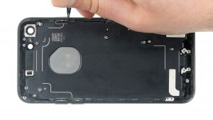
Removing the rear case screws
-
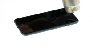
Heating up the display
-
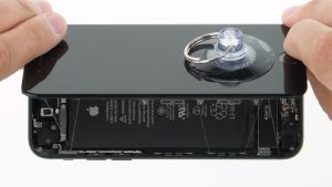
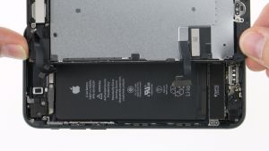
Lifting up the display
-
Detaching the display
-
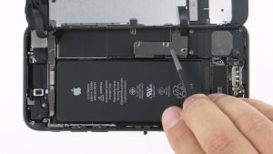
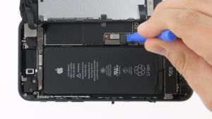
Disconnecting the battery connector
-
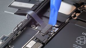
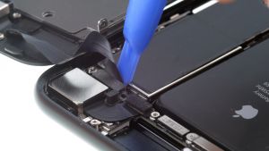
Detaching the display connectors
-
Detaching the FaceTime connector
-
Removing the Taptic Engine
-
Removing the battery
-
Removing the speaker
-
Removing the iSight camera
-
Detaching the connector of the volume control cable
-
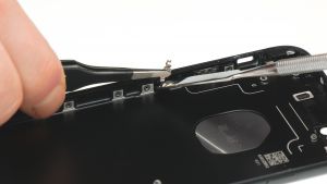
Detaching the cover of the Wi-Fi antenna
-
Removing the Wi-Fi antenna
-
Removing the SIM tray
-
Detaching the logicboard
-
Removing the Lightning connector
-
Detaching the volume control cable
-
Removing the guide rail for the iSight camera
-
Detaching the mounting clamps
-
Removing the sleep/wake and volume button
-
Preparing the new back cover
![iPhone 7 - Preparing the new back cover 01]()
![iPhone 7 - Preparing the new back cover 02]()
-
-
Installing the sleep/wake and volume button
-
Installing the retaining brackets
-
Installing the guide rail for the iSight camera
-
Attaching the volume control cable
-
Installing the Lightning connector
-
Inserting the logicboard
-
Inserting the SIM tray
![iPhone 7 - Inserting the SIM tray 01]()
![iPhone 7 - Inserting the SIM tray 02]()
-
-
Attaching the connectors
![iPhone 7 - Attaching the connectors 01]()
![iPhone 7 - Attaching the connectors 02]()
-
-
Installing the Wi-Fi antenna
-
Installing the antenna cover
-
Installing the bracket plate
-
Connecting the iSight camera
-
Installing the speaker
-
Preparing the battery
![iPhone 7 - Preparing the battery 01]()
![iPhone 7 - Preparing the battery 02]()
![iPhone 7 - Preparing the battery 03]()
![iPhone 7 - Preparing the battery 04]()
![iPhone 7 - Preparing the battery 05]()
![iPhone 7 - Preparing the battery 06]()
![iPhone 7 - Preparing the battery 07]()
-
-
Inserting the battery
![iPhone 7 - Inserting the battery 01]()
![iPhone 7 - Inserting the battery 02]()
![iPhone 7 - Inserting the battery 03]()
-
-
Inserting the Taptic Engine
-
Attach the adhesive frame
-
Attaching the the FaceTime connector
-
Connecting the display
![iPhone 7 - Connecting the display 01]()
![iPhone 7 - Connecting the display 02]()
![iPhone 7 - Connecting the display 03]()
![iPhone 7 - Connecting the display 04]()
![iPhone 7 - Connecting the display 05]()
![iPhone 7 - Connecting the display 06]()
-
-
Attaching the battery connector
-
Attaching the display
![iPhone 7 - Attaching the display 01]()
![iPhone 7 - Attaching the display 02]()
![iPhone 7 - Attaching the display 03]()
![iPhone 7 - Attaching the display 04]()
![iPhone 7 - Attaching the display 05]()
-
-
Fastening the rear case screws


The right tools for your repair


Similar guides
You might also be interested in these guides.


You might be interested in